Diagram Switched Low Pass L Network
Free Printable Diagram Switched Low Pass L Network
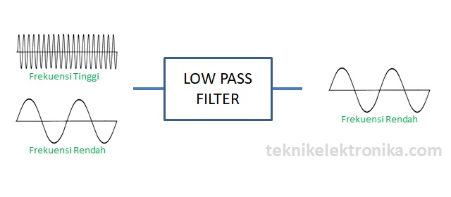
Pengertian Low Pass Filter Lpf Atau Tapis Lolos Bawah Rc Dan Rl
Low Pass Filter Explained

Low Pass Filters And High Pass Filters Rc And Rl Circuits Youtube
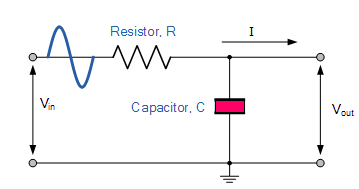
Rc Low Pass Filter Circuit As Integrator Step Input
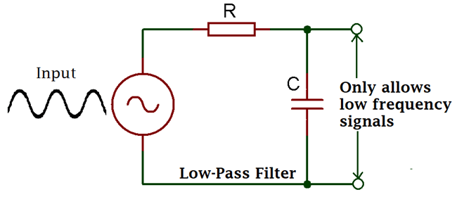
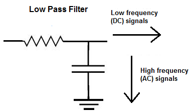
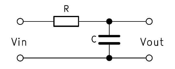
Passive Low Pass Filter

Passive Band Pass Filter Circuit Design And Applications
Servicing is required when the apparatus has been damaged in any way such as power supply cord or plug is damaged liquid has been spilled or objects have fallen into the apparatus the apparatus has been exposed to rain or moisture does not operate.
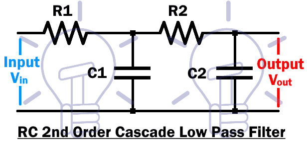
Diagram switched low pass l network. Basic lumped circuit matching using the l network. Level control mode options for on the fly volume adjustments of all zones together or individually. The following two graphs plot the frequency response for the basic switched capacitor low pass filter from figure 15 3 2 with the value of c 1 equal to 100pf and with the value of c 2 equal to 4 7nf for a c 1 to c 2 ratio of 1 to 47. Packet switching is a method of grouping data that is transmitted over a digital network into packets packets are made of a header and a payload data in the header is used by networking hardware to direct the packet to its destination where the payload is extracted and used by application software packet switching is the primary basis for data communications in computer networks worldwide.
When vdd is less than 2 4v an internal source is switched to vbat. This would not be a problem if the vhf energy had a resistive load however the typical output circuit is a hf low pass pi network which blocks vhf so the vhf energy runs amuck and causes arcing. There are two ways to avoid launching vhf parasitic oscillations. For any one given antenna and frequency once a circuit is selected from the eight possible configurations of which six are shown in the diagram below only one set of component values will match the in impedance to the out impedance.
The imbalanced l network forms the basis for all of the antenna tuners that are currently being sold. An l network is the simplest circuit that will achieve the desired transformation. Computer network by kanodia publication free download as pdf file pdf text file txt or read online for free. Selectable de bounce period 35ms or 2s.
In short order the amplitude of the vhf signal becomes large. Frequency response for f clock equal to 100 khz 200 khz and 500 khz. It is also used to build high pass low pass and band pass filters. The l network is the basic rf resistance or reactance plus resistance impedance z transformation tool.
Figure 15 3 3 plots the amplitude vs. Pass crossover with frequency selection off 60 80 100 150 hz subwoofer zone outputs equipped with a 500 hz low pass crossover configureable zone feature control options include. Refer all servicing to qualified service personnel. Computer nw book with all info.
The receiver front end has a 0 30 mhz filter low pass filter shown as the left most block in the diagram above. Unplug this apparatus during lightning storms or when unused for long periods of time. This is a simple four section filter that was interestingly described by wes hayward on his own website the original article that had very useful information about building filters on pcbs. Available event detection interrupt output.
When the supply from vbat spi interface are disabled.

3 Way Crossover Design Example Electronic Circuit Projects

Fundamental Physics Electronics Rl Circuit Wikiversity
Explain Various Types Of Low Pass Filters Electronics Post

Pin En Power Amplifiers
Types Of Passive Low Pass Filters Rl And Rc Passive Filters

How To Connect A Portable Generator To The Home Supply 4 Methods

Low Noise Pre Tone Control Circuit Using 4558 Ne55532

Foarte Util Electronics Circuit Electronic Schematics Audio
Low Pass Filter Calculator Electronicbase
Electronic Circuits Linear Wave Shapping Tutorialspoint

Subwoofer Crossover Filter Circuit Rangkaian Elektronik
Difference Between High Pass And Low Pass Filter With Comparison

Pin On Synaesthetics

