Visualize Lead And Lag Project Network Diagram
Free Printable Visualize Lead And Lag Project Network Diagram
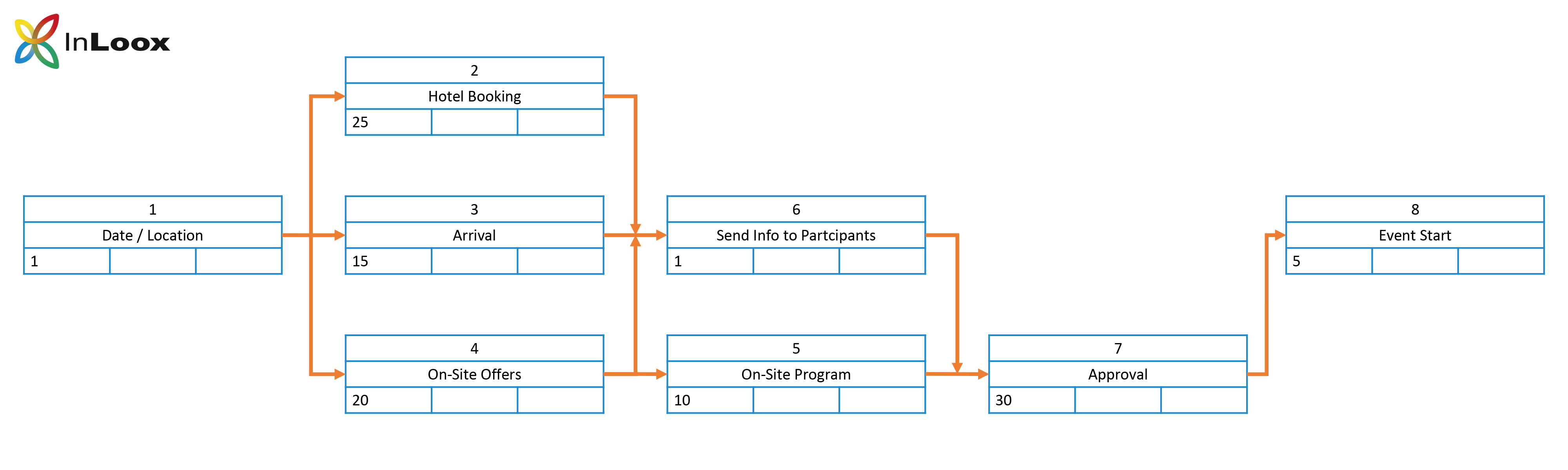
Back To Basics Part 10 How To Create A Project Network Diagram
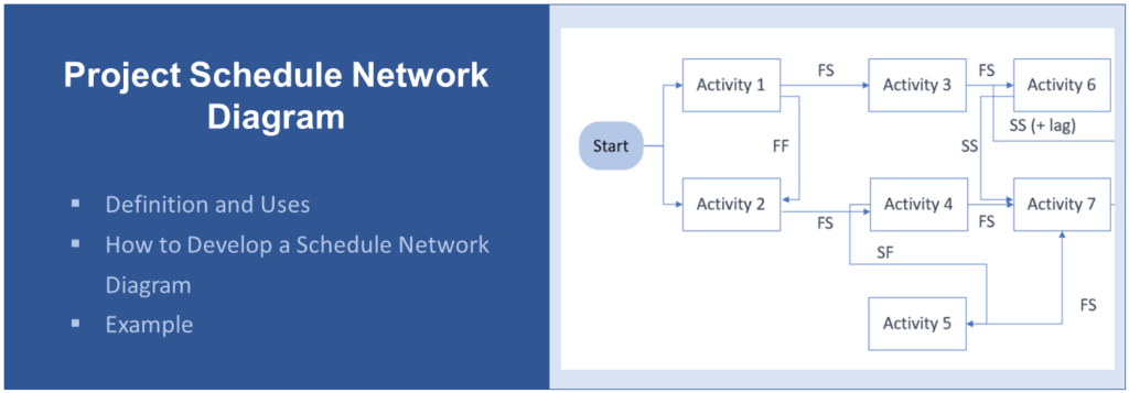
Project Schedule Network Diagram Definition Uses Example

Network Diagram Example Telecommunnications Network Architecture
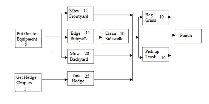
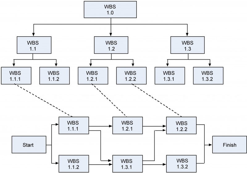
Work Breakdown Structure And Arrow Diagrams Nais Lab

Are You Making Proper Use Of Dependencies And Constraints
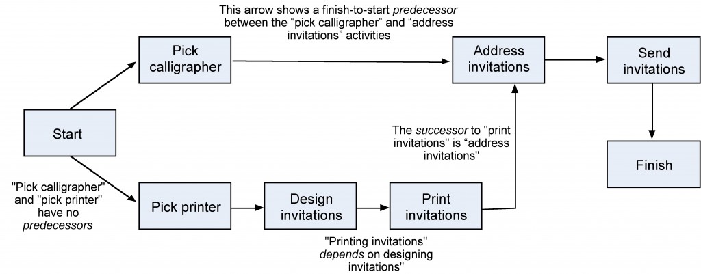
Creating The Network Diagram Open Textbooks For Hong Kong

Lead and lag in project activities are easy concepts.
Visualize lead and lag project network diagram. Even though during my coaching sessions i see a lot of confusion around them. If you follow the arrows and take the types of relationships as well as the leads and lags into account you can determine the duration of a path and eventually identify the critical path of a project. After you finish an activity or reach a milestone you can proceed to the next activity or milestone as indicated by the arrow s. Lead and lag is key theory for your pmp.
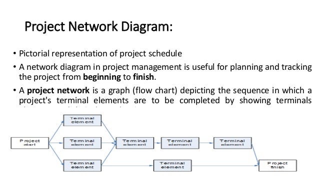
Regardless of the type of planning methodology or technique such as agile or rolling wave the concept of leads and lags is applicable. Project activities are dependent on each other depending on the logical relationship they have as defined by the precedence diagram. A schedule network diagram is a useful visualization of the sequence and logical relationships of activities in a project. Let s decode these confusions here starting from lag time in project management.
Among the numerous parameters that utilized in the project schedule lead and lag are the essential ideas that are also in use. The most common method for creating a network diagram is precedence diagramming method which is abbreviated as pdm. Lead time and lag time both play an important role in network diagram development. When sequencing the activities the relationships and dependencies between the activities should be kept in mind.
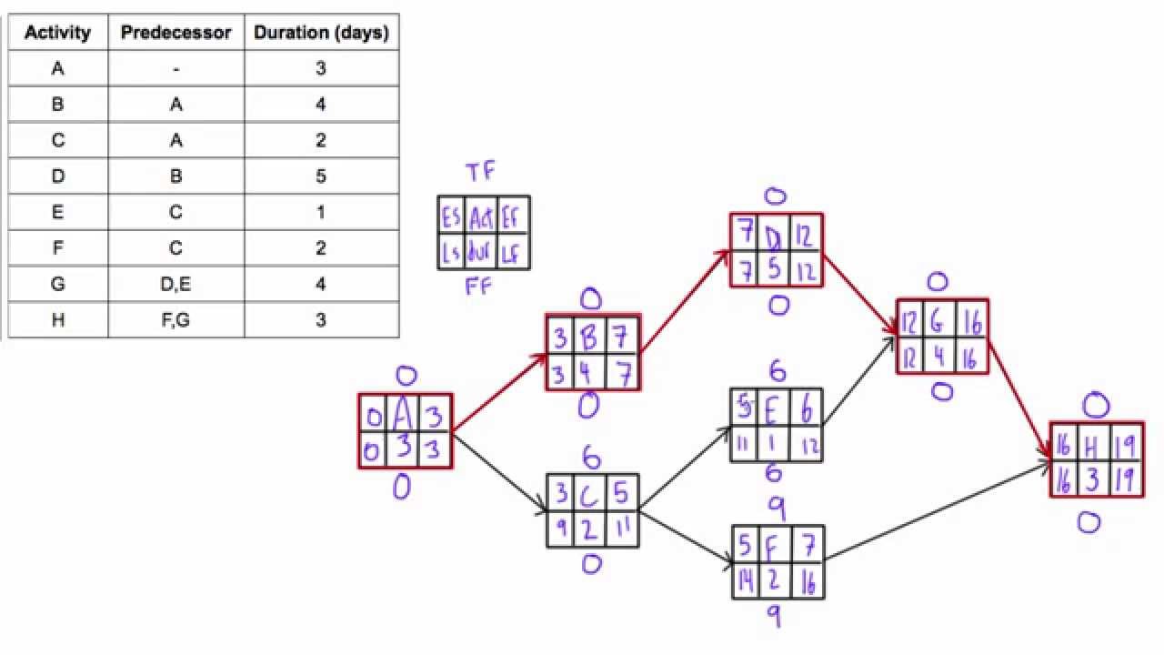
Project network diagram representation of lag in our example the project team would need 6 days to complete these activities. In this blog post i will explain lead time and lag time with simple real world examples. Although the concept is easy a few people still find it difficult to understand. Reading a network diagram is a snap if you apply these two rules.
By learning the concept of leads and lags you can create a more reliable schedule. Project schedule management lead and lag duration. Amidst every set of activities in the project network diagram pnd are the relationships that depict how and when a successor and paired activities can start. During sequence activities process which is the third process of time management the activities of a project are sequenced and a network diagram is created.
If the said fs relationship was without any lag the project team would have needed 5 days. Especially when we use these concepts in network diagrams and with a different type of relationships. Lead vs lag lead time lag time in scheduling. While creating a work schedule or a network diagram professionals often use many terminologies such as lead time lag time total float free float etc these scheduling tools are used along with activity relationships in order to model the real nature of work to be performed.
A network diagram helps you visualize all aspects of a project that you need to monitor.
Network Diagram An Important Tool In Project Management
An Overview Of Network Diagrams In Project Management Brighthub

Fishbone Diagram Example Product Failure Cause And Effect

Fishbone Diagram Example 2 Custom Orders Custom Graphic
Determine Total Float Free Float Aka Slack Of Activities In
Figma Templates For Data Design And Visualization Data

Network Diagram Networking Basics Computer Network Computer
10 Project Schedule Planning Project Management

Isometric Network Diagram By Bobby Hodges Conte Internet

Project Time Management Major Topics Pmp Pmo Pmi
Software Project Scheduling Diagrams

Pin On Technology Trends

Network Topology Is The Arrangement Of The Various Elements Links

