Combinational Network Timing Diagram

Free Printable Combinational Network Timing Diagram

Cctv Balun Wiring Diagram Fitfathers Me Inside Coachedby For

Cctv Balun Wiring Diagram Fitfathers Me Inside Coachedby For

Solved 1 Timing Analysis Of Combinational Logic Networks

Solved 1 Timing Analysis Of Combinational Logic Networks

Simple Sequential Logic Circuit With Timing Diagram Download

Simple Sequential Logic Circuit With Timing Diagram Download

Combinational Network Design Springerlink

Combinational Network Design Springerlink

What Is Human Machine Interface Hmi Human Machine Interface

What Is Human Machine Interface Hmi Human Machine Interface

Lecture 11 Timing Diagrams Hazards Ppt Video Online Download

Lecture 11 Timing Diagrams Hazards Ppt Video Online Download

Lecture 11 Timing Diagrams Hazards Ppt Video Online Download

Answer to need block diagrams combinational logic sequential logic timing logic state diagramsstate tablevhdl w waveforms.

Combinational network timing diagram. The xor gate has a contamination delay of 2 units and a propagation delay of 3 units. Load the following circuit in the d dcs with a click on the figure. Compile a truth table of the network then just by looking at the table design a simpler logic network with the same behavior click here to open in the d dcs the schematic to be completed verify the equivalence of the two networks using the timing diagram simulation. A suitable test sequence is available in the timing diagram window.

Updated 08 14 2019 07 04 am. Using the functional simulation compile a truth table with the results of the functional simulation. Given the following combinational network click on the figure to open the schematic in the d dcs. This article will explore timing diagrams pertaining to combinational circuits with gate delays static 0 and 1 hazards as well as switching functions.

Combinational circuit and timing diagrams created 02 11 2016 08 15 am. Draw the timing diagram for the following combinational circuit. However the inverters have a contamination delay of 1 unit and a propagation delay of 2 units. You can make changes to this design and upon clicking the save as button a copy will be created.
Understanding Clock Networks Smarttime

Understanding Clock Networks Smarttime

Timing Diagram Showing The Same Logic Block Operating In A

Timing Diagram Showing The Same Logic Block Operating In A

1n4733a 5 1v Zener Diode Circuito Electronico Electronica

1n4733a 5 1v Zener Diode Circuito Electronico Electronica

1 Sequential Logic Networks I Motivation Examples Output

1 Sequential Logic Networks I Motivation Examples Output

Topics Combinational Network Delay Ppt Video Online Download

Topics Combinational Network Delay Ppt Video Online Download

Proceedings Of The Ieee Vol 89 No 5 May 2001 Clock

Proceedings Of The Ieee Vol 89 No 5 May 2001 Clock

Lecture 7 Sequential Networks Ppt Download

Lecture 7 Sequential Networks Ppt Download

1 Combinational Logic Network Design Chapter 4 Continued

1 Combinational Logic Network Design Chapter 4 Continued

23 Good Sample Of How To Draw Network Diagram In Excel Design

23 Good Sample Of How To Draw Network Diagram In Excel Design

Solved 1 1 Pts A A Timing Diagram Of A Digital Circu

Solved 1 1 Pts A A Timing Diagram Of A Digital Circu

Master Slave Jk Flip Flop Geeksforgeeks

Master Slave Jk Flip Flop Geeksforgeeks

1 1 5 Marks Construct A Jk Flip Flop Using A T Chegg Com

1 1 5 Marks Construct A Jk Flip Flop Using A T Chegg Com

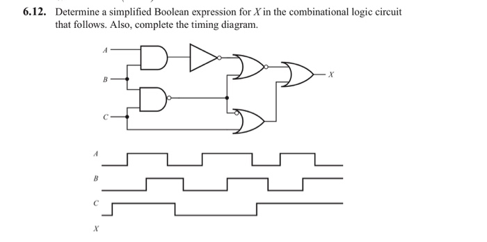
Solved Determine A Simplified Boolean Expression For X In

Solved Determine A Simplified Boolean Expression For X In

Combinational Circuit Design And Simulation Using Gates

Combinational Circuit Design And Simulation Using Gates

Source : pinterest.com