Block Diagram Of Voltage Source Network Interface
Free Printable Block Diagram Of Voltage Source Network Interface

Automatic Transfer System Explained In Details

Green House Monitoring Using Arduino Arduino Microcontrollers

Block Diagram For Grid Interface With Wind Turbine Source 56

Ti Active Noise Cancellation Block Diagram

Block Diagram Of Conventional Ups System Download Scientific Diagram

The Best 12 Isometric Network Diagram For You Softwaredesign
Reinforced isolated modulator with ldo regulator 250mv input and cmos interface.
Block diagram of voltage source network interface. It is shown in block diagram form in figure 9 4. The v dd voltage is monitored and it switches to the backup power supply by the automatic operation. The simulation engine provides fast and accurate solutions for linear nonlinear continuous time discrete time time varying and hybrid system designs. The block diagram of the interface board for connecting sensors with wns is depicted in fig.
The visual block diagram interface offers a simple method for constructing modifying and maintaining complex system models. We do this so that more people are able to harness the power of computing and digital technologies for work to solve problems that matter to them and to express themselves creatively. I 2 c bus interface fast mode 400 khz. Only two of the elements in the diagram the tmr2 register and the prescaler actually relate to the conventional timer function.
Amlogic s905x3 specifications block diagram a few days ago we wrote about upcoming quad core cortex a55 processors from amlogic with s905x3 s905y3 and s905d3 socs. Timer 2 is a pure timer so is driven only from the internal oscillator shown at the right of the diagram. Quickly understand overall system functionality. The fig shown the block and circuit diagram of output module.
When logic high signal comes from the processor the led is on light strike to phototransistor. Output frequency is selectable from 32 768 khz 1024 hz 1 hz. Document includes block diagram 450748 doc. Auto power switching function.
Mil std 1553 is a military standard published by the united states department of defense that defines the mechanical electrical and functional characteristics of a serial data bus it was originally designed as an avionic data bus for use with military avionics but has also become commonly used in spacecraft on board data handling obdh subsystems both military and civil. Which become in conduction region give a triggering pulse to at the gate of. The 16f87xa timer 2 is a simple 8 bit device. The sensor s1 is connected to 12 24 v dc power supply p as input.
Today we got a little more information with a product brief including the main features and a block diagram. Plc output module block diagram. Backup power supply switching voltage 1 2 v min. This board consists of interface circuit ic and eprom connector e.
Single phase inverter reference design with voltage source and grid connected modes.

Building Internet Of Things Using Attiny2313 Visit Http Xanthium

Pid Block And Manual Pid Matlab Answers Matlab Central

At89c2051 Digital Scales Circuit Atmel Digital Scale Circuit

Single Phase Variable Frequency Drive Vfd Circuit Simple Circuit

The Schematic Diagram Of The Power Supply Unit Is Shown Below

Block Diagram Of The Soft Starter Download Scientific Diagram

Solid State Relay With 16a Scr Optical Trigger Circuit Diagram
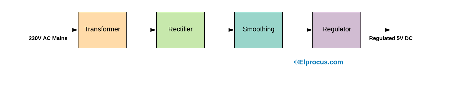
Power Supply Classification And Its Various Types

Block Diagram Of A Diesel Generator Power Conversion System

Simple 12v 2a Power Supply Circuit Eleccircuit Com Power

Thevenin S Theorem Easy Step By Step Procedure With Example

24 Awesome Free Diagram Software Windows Workflow Diagram

Understanding Operating Systems Pc Repair Laptop Repair

